|
The Ports
The Motherboard
The Processor
| | PC Components - A Technical Insight
The following pages contain technical information about the main components
found in a standard personal computer.
Since the release of the original IBM PC new and enhanced components have
been added to the basic design. The rapid advances of the personal computer were
partly because of software demands placed on hardware, such as graphical user
interfaces (GUI's) or memory hungry applications and new technologies and design
techniques processor, motherboard, component and peripheral manufacturers standardized.
Overview
The components I am referring to are usually integrated on the motherboard.
The processor and support circuits, memory (RAM and ROM), the input/output
interface (including the serial and parallel ports, keyboard interface, disk
interface, graphics interface, etc) and buses (the data bus, the address and
control bus). There was no real time clock on the original PC and had to be
manufactured on an expansion card and placed in one of the motherboard expansion
slots. (One of the early upgrades available for PC compatibles).
A computer carries out a series of commands called a program. The processor is
designed and organised with the ability to do this. The processor can also
read and write to memory because instructions and data used by programs is
temporarily held there, secondly the processor is capable of understanding and
carry out the series of instructions. The processor is also able to instruct
other components on what to do and therefore manage the computers operation.
Although the processor makes a distinction between instructions and data ,
memory does not (apart from cache). Memory is temporary (unlike ours) and needs
constant reminding by dedicated circuitry (except for static ROM). Most memory
needs a constant power and hence is referred to as volatile, memory that does
not need power to retain data is known as non-volatile (straight forward when
there was only one main type of ROM and RAM). Memory is the workspace that
programs use when running. The size of workspace is equivalent to the amount of
memory installed. The memory can be written to, read from and over written
(there is no need for the memory to be cleared first), by both the processor and
the input / output devices.
The input/output devices form a window between the system and the outside
world allowing communication with the memory and processor. A bridge between the
user and the computer. I/O devices (peripherals) include the keyboard, the
monitor, mouse, printer, modem, network and disk storage devices.
PC components are connected together by the bus architecture which can be
thought of as a highway along which devices communicate. The original PC bus
architecture was 8 bits wide and could transfer about 1MB per second compared to
a modern 64 bit bus which can transfer data in excess of 500 MB per second.
Modern applications place a heavy demand on the bus architecture. New bus
designs made applications not previously possible, such as multimedia
available on the PC. Pentium processors are able to support multiprocessor buses
and many motherboard designs are able to accommodate two or more processors.
When systems have multiple bus types in a single design there are devices that
bridge between the bus types. New
buses will appear that support new designs such as SIMPL, HydraXS and VBus.
The computer case or box houses the motherboard, devices, drives and a power
supply (PSU). There are several popular types of case available, such as
desktop, mini-desktop, slimline desktop, tower, mini tower and midi tower. All
the components need power to function. AC current is converted to DC and output
at voltages of 5, 12 and 3.3 and a fixed polarity of either positive or
negative. Power supply units are rated in watts.
To better understand how the industry arrived at its present state of
supporting multiple processor types and speeds, multiple physical packaging
styles and bus architectures read The Personal Computer
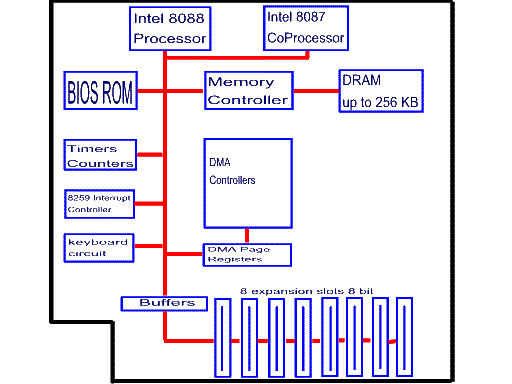
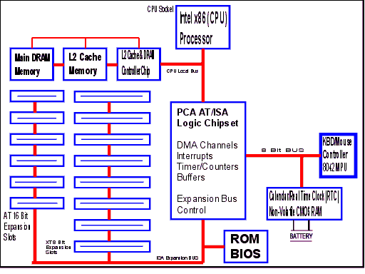
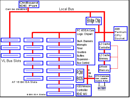
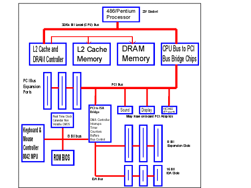
guide. Below are block diagrams illustrating the layout of the different bus
architectures.
The PC and PC XT block diagram :

A typical system used four expansion slots
1. Floppy Disk Controller
2. Hard Disk Drive controller
3. The Display adaptor
4. Combined Serial and Parallel Port Adaptor
The PC AT ISA block diagram :

8 slots with two usually used
1. EGA or VGA display controller adaptor
2. Multi I/O Port adaptor with
- 2 serial ports
- a parallel port
- floppy disk drive interface
- IDE interface for hard disk drives
- a Game Port
VESA Local Bus system block diagram :

A typical system may use 2 VL expansion slots
1. Multi I/O with EIDE
2. SVGA (Super-Video Graphics Array) Display Adaptor.
PCI ISA Bus Block diagram :

One of the PCI slots is placed close to one PCI slot and share the (but not
at the same time) a back-plate.
Some motherboards only offer two ISA slots and
as many as five PCI slots.
|
![[Company Logo Image]](images/webgfx-6236316.jpg)